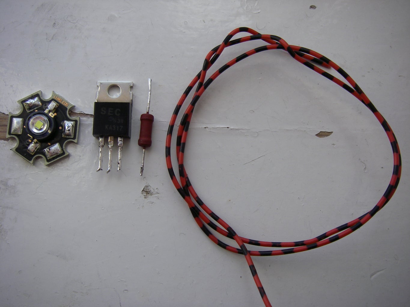
Super Simple High Power LED Driver 3 Steps Circuit Diagram - consistent LED performance with any power supply and LED's - costs about $1 - only 4 simple parts to connect - efficiency can be over 90% (with proper LED and power supply selection) - can handle LOTS of power, 20 Amps or more no problem. - low "dropout" - the input voltage can be as little as 0.6 volts higher than the output voltage.
Now coming back to our LED driver subject, in this post I will elucidate two simple methods of designing LED drivers, 1) SMPS method, 2) capacitive power supply method. Warning: Circuits I have explained below are not isolated from mains AC, and therefore are extremely dangerous to touch in the powered and open condition. Constant Current Driver: The driver ensures that the LED gets a constant current regardless of voltage fluctuations. This is ideal for LEDs that require a fixed current for proper operation. Constant Voltage Driver: The driver maintains a steady voltage but allows the current to fluctuate based on the load.This is typically used when the LED needs a specific voltage, regardless of the current The LED voltage was ~23V, the power supply 24V. So no other way than to use a buck-boost regulator here. Yes, in essence it's a boost regulator, but instead working to GND you work to 24V

High Power LED Driver Circuits : 12 Steps (with Pictures ... Circuit Diagram
A constant-current power regulator is a must for LED illumination because a high-power LED's current may double with a voltage increase of only 10% - meaning that there is a high possibility of damage to the LED. The power stage's topology and flexible dimming control are two main considerations for choosing LED illumination drivers, as The high-quality LED driver can always control the line and load regulation to <=1% value. g. Programmability of LED Driver integrated controllers or sensors so as to provide smart systems or functions to the end-users and the 12V/2~4W power from LED Driver can make the design much easier compared with using an AC adapter to create the 12V note demonstrates a minimal parts count driver/control-ler for a high-power (1W or greater) LED. The circuit is based on a buck topology switching power supply using the on-chip comparator peripheral within the PIC12F675 PIC® microcontroller. The switching power supply design ensures efficient power transfer between the system battery and the
The main consideration when deciding on how to drive LEDs is how much power loss is acceptable. In battery-powered devices, this power loss equates to diminished battery life. In high-power LED applications, it equates to heat generated. Before choosing how to drive the LEDs, have an idea of how much power your design allows you to dissipate.
